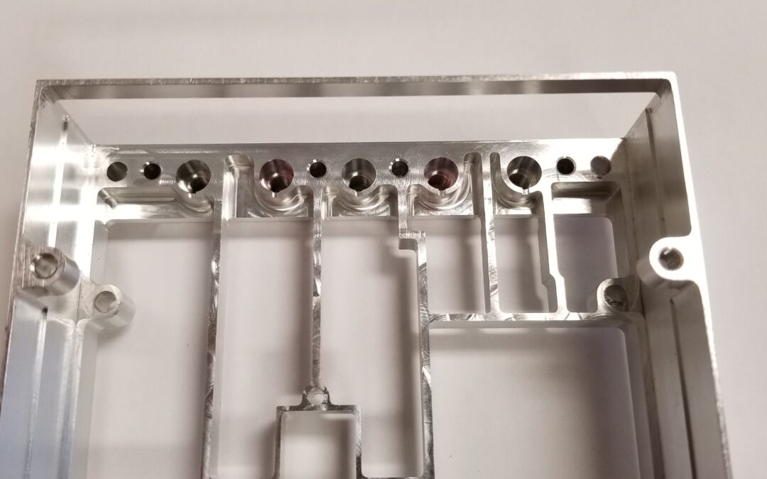
Customers often ask us to produce parts with internal features that have relatively small radius corners. These small corners should only be necessary for clearance of mating parts or very particular applications. However, designers and engineers will still include these features on many of the parts that they need built, not realizing the difficulty this can add to the machining process.
In the aerospace machining world, machine shops need to be able to create all kinds of difficult features, usually to tight profile tolerances. When it comes to small radius corners of internal pockets and feature, there are a few parameters to consider:
- End mill size required (using something smaller than the required radius)
- Length to diameter ratio of the endmill needed
- Cutting Strategy
With these parameters in mind, it is possible to achieve tight tolerance on inside corners. Here are a few tips to overcome the challenge of machining tight corners.
Selecting the Right Tool Size for Machining Small Radius Corners
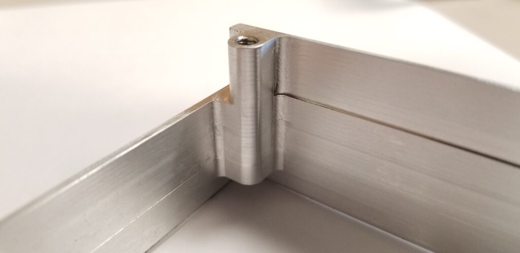
Selecting the right end mill for the job is a critical aspect when machining tight corner radius features. Usually while you are programming your parts, the pocket is roughed out with a large, stout endmill for a speedy material removal. You will need to work your way down to a smaller end mill to be able to get into the tight corner. When selecting the cutter size for the final corner, if possible, you should always use an endmill with a smaller diameter than the equivalent corner radius of your feature. For example: if you have a pocket with .063 radius corners, DO NOT use a 1/8 end mill (this creates a .0625 radius). You need to select a smaller endmill such as a 3/32 (.0938) or even 7/64 (.1094) to perform this operation. The smaller cutter diameter allows the part to “walk around” or interpolate the corner, rather than getting to the corner and forming the radius due to the cutter size. Using an endmill with the same radius as the corner you are cutting, will cause chatter,which is typically unacceptable in aerospace parts or any part requiring good surface finishes, and will decrease the life of the tool.
Consider the Length Diameter Ratio
Most endmills have a standard cutting length to diameter ratio of 3:1. The engineering team behind the parts you are making should take this into consideration, however, if not, straight away you may be selecting tools that have a non-standard LoC (length of cut) or reach (axial distance that an endmill can cut). As above, start by selecting the ideal diameter, and then look for tooling with the desired cut length. For non-standard,long LoC or Reach – or both, we like to use Harvey Tool for our tool selection.
Overcoming Challenges of Tight Corner Machining
While there are many instances where the part can be designed to avoid small radius corner machining, there are times when a part will require small corner radius features that are unavoidable. When facing these parts, there is a strategy Ultra Precision has had success in using to overcome the challenges tight corner machining often presents.
Strategy:
If you are able to use an endmill with nearly a 3:1 length to diameter ratio, the machining process is pretty straight forward. In aluminum, you can essentially cut the corner feature using a roughing pass followed by a finishing pass; both at full axial depth. However, as different variables: Harder material alloys; length-to-diameter ratios; size of the radius; cutter availability; and price begin to change, increases in difficulty can result.
Ideally, if the cut becomes difficult, rough out the pocket or feature with a large tool, then come in with a smaller tool to do the finer work. We like to use an adaptive, continuous cut, style of material removal for the roughing phase.
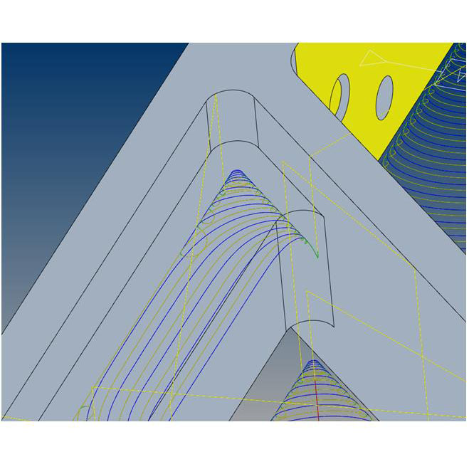
After this is done, we recommend using a “rest material strategy” to focus on the corners that still have material left from the larger cutter.
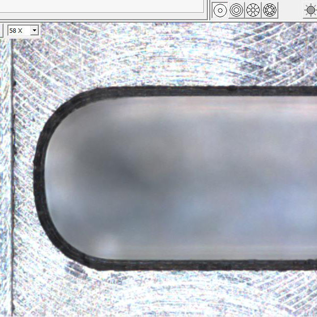
For the final step, you need to slowly remove material in the corners, using light step-overs and multiple finish passes. Finish passes or even spring passes, cutting at the same position multiple times to achieve a closer tolerance, are usually required to get a radius in-tolerance. See pictures below:
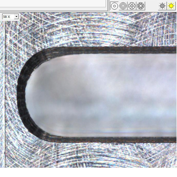
This was the difference between one finish pass and multiple spring passes. Notice the chamfer is larger on the left picture. That is because there is more material in this corner than intended and the chamfer cut larger there; revealing an issue. The tight tolerance profile for this part only came into tolerance once the spring passes were applied.
When designing your CNC machined parts, you will need to balance your requirements with the constraints that come from tooling. However, corner radii is also an important consideration to creating machined components and enclosure designs. The corner radii complexity will directly affect the machining process, time, and ultimately the cost of the project.
Ultra Precision Machine is well-versed in machining tight tolerance features, including difficult corner geometry. Contact us to discuss your part design.
 Made in the USA
